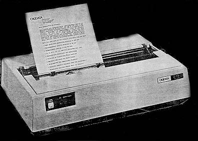
 Microline 84
 |
Language: Okidata
standard Technology:
monochrome 9-pin dot-matrix
Speed: 200cps draft,
50 cps NLQ
Graphics: 240 dpi
|


Internal font available in
Draft and Correspondence qualities, 10 cpi, 12 cpi, 17 cpi,
emphasized and expanded.
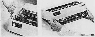
Tractor Feeding
Single sheet paper cannot be
used when the tractor assembly is in place.
- Turn the printer's
paper lock release lever to the front (open) position.
- Hold the tractor side
plates on the right and left of the tractor unit with
both hands, and engage the cutouts in the tractor side
plates with the bar shaft of the printer. (A)
- Pivot the tractor
assembly towards you until the clamp lever snaps into
place on the platen bearing. (B)
- Paper should be fed
behind column indicator bar.
- Adjust for paper width
by pulling lock lever towards you and sliding tractor
sideways. Push lever back to lock in place.
NOTE: Do not move left
tractor beyond 2" to the right. The paper out switch
function could be affected.
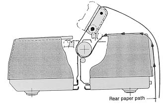
When using the tractor feed,
disengage the paper lock release lever (A) by shifting it toward
the front of the printer. This lever should be pushed towards the
rear of printer only when friction feed is desired for single
sheet feed.
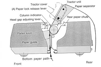
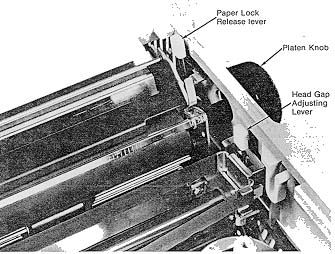
Paper Adjustment
- Paper Lock Release
Lever - Push towards back when using cut sheets for
friction feed. Pull towards front whn using sprocket
paper for tractor feed.
- Head Gap Adjusting
Lever - Selects printing pressure according to paper
thickness.
- Platen Knob - For
manually feeding paper.
- Setting Form Length -
If the printer is OFF: set the FORM LENGTH dial to the
number of the desired page length. Adjust the paper to
where you want printing to start. When you turn the
printer on, the page length and top of form will be set
automatically.
If the printer is ON: make sure the SEL lamp is out
(press SEL switch if necessary). then set FORM LENGTH and
first line to be printed as above and press the TOF SET
switch to set the page length and top of form.
Dial
Position |
Paper
Length |
6 LPI |
8 LPI |
| 0 |
3 inches |
18 lines |
24 lines |
| 1 |
3.5 inches |
21 lines |
28 lines |
| 2 |
4 inches |
24 lines |
32 lines |
| 3 |
5.5 inches |
33 lines |
44 lines |
| 4 |
6 inches |
36 lines |
48 lines |
| 5 |
7 inches |
42 lines |
56 lines |
| 6 |
8.5 inches |
48 lines |
64 lines |
| 7 |
11 inches |
66 lines |
88 lines |
| 8 |
12 inches |
72 lines |
96 lines |
| 9 |
14 inches |
84 lines |
112 lines |
Optional Cut Sheet Feeder
The cut sheet feeder makes
it easy to print on standard paper and letterhead stationery.
Paper handling is controlled automatically by the cut sheet
feeder, so you can print long documents without stopping to
insert a new page.
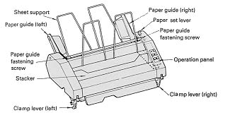
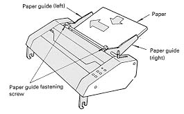
Paper Loading
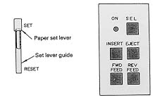
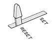
- Set the paper set lever
of the cut sheet feeder to the RESET position.
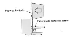
- Slide the left paper
guide to the left end. (The paper guide can be moved by
loosening the paper guide fastening screw, and can be
fastened by tightening the screw.) With this paper guide
position, the first printing character is printed 0.5
inch inside the paper left end.
- Set the right paper
guide roughly to the paper right end.
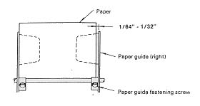
- Riffle a batch of new
papers, place them between the left and right paper
guides, and push them slightly to the left and front.
- Adjust the right paper
guide position so that there is a gap of 1/64" to
1/32" between the guide and the paper right end, and
fasten the guide with the fastening screw.
- Set the paper set lever
to the SET position. Do not release and withdraw your
hand until the set lever is firmly engaged in the SET
position.
NOTE: Precautions for paper
installation:
- The cut sheet feeder
can hold a 5/8" stack of paper (about 200 sheets) at
one time. If paper is set exceeding 5/8", this may
cause paper jam or paper feed error.
- Only one-part paper can
be used; no multiple-part paper can be used.
- Do not use wrinkled,
folded or bent paper.
- Do not use paper of
differing sizes.
- Prior to setting a
batch of new papers, riffle them well so that the sheets
are separated from one another.
Paper Positioning
- Set the cut sheet
feeder in select state (SEL lamp lit) and press the
INSERT button to feed a sheet to the front of the platen.
- Position the paper at
the desired printing start line using the FWD FEED and
REV FEED buttons.
FWD FEED button moves the paper up 1/144th inch when you
press it. Hold the button down for continuous feeding.
REV FEED button moves the paper down 1/144th inch when
you press it. When the button is held down, the paper
moves in 1/3-inch increments. Be sure to allow at least a
1-inch margin at the top of the paper.
- Make sure the printer
is deselected (SEL light out) and press the TOF SET
button. This will set Top of Form at the current paper
position when the printer is selected.
Setting Form Length
You can set the from length
using either a software command or the FORM LENGTH dial on the
printer. If you use the FORM LENGTH dial, make sure the printer
is deselected (SEL lamp out), then set the dial for the desired
form length according to the table below. The form length will be
set when the printer is selected.
| Dial Position |
Paper Size HxW |
6 LPI |
8 LPI |
| 0 |
|
32 lines |
42 lines |
| 1 |
|
49 lines |
66 lines |
| 2 |
|
38 lines |
51 lines |
| 3 |
|
59 lines |
78 lines |
| 4 |
|
49 lines |
66 lines |
| 5 |
|
75 lines |
99 lines |
| 6 |
8.5" x
11" |
40 lines |
53 lines |
| 7 |
11" x
8.5" |
55 lines |
73 lines |
Manual Operation for
Printing Single Pages
- Set both printer and
cut sheet feeder in the deselect state (both SEL lamps
off).
- Press the INSERT button
to move the printhead to the center of the platen.
- Insert a sheet of paper
along the upper sheet support.
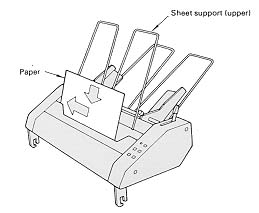
- Set the paper at the
left edge at a right angle to the feed direction.
- Turn the platen knob to
advance the paper to the front of the platen and set the
paper to the desired location.
- Press the INSERT button
to move the printhead to the home position.
- Press the printer SEL
button to set it in the select state (SEL lamp on). The
printer is now ready to receive and print data.
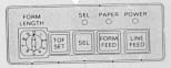
- ON/OFF switch -
Switches AC power on and off.
- POWER lamp - Lights
when power is on.
- FORM LENGTH SELECTION
dial - Used for selecting page length.
- SEL LAMP - When the
lamp is lit, it indicates that the printer is ready to
receive data from the computer. When the lamp is not lie,
the printer cannot receive data. When paper runs out,
this lamp foes out and data cannot be received. The lamp
goes on automatically when the printer is turned on.
- SELECT SWITCH - Pushing
this switch will alternately turn the SELECT lamp on or
off.
- TOF SET SWITCH - The
TOF switch allows you to set the position where the first
line of data will be printed on the page. This switch is
not active when the select lamp is lit.
- FORM FEED SWITCH - When
the switch is pushed, paper is fed to the next top of
form position. This switch is not active when the select
lamp is lit.
- LINE FEED SWITCH - Each
time this switch is pushed, paper is fed one line upward.
This switch is not active when the select lamp is lit. It
is also used to start the local print test by holding it
down when powering up the printer and then releasing the
pushbutton.
- PAPER LAMP - Lights
when new paper should be inserted.
Function Switch Settings
To gain access to the
function switches, pull off the platen knob and access cover and
unscrew the two hold-down screws inside the front of the upper
cover using a phillips screwdriver with at least a 4" shaft.
Then lift up the front of the upper cover and release it from the
hooks in the back of the base. The function switches are located
on the control circuit board in the back of the printer.
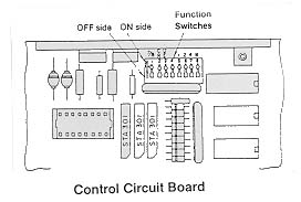
The function switches have
two different sets of labels, one on the switch bank itself and
one silkscreened on the circuit board. Be sure you are setting
the correct switches. Whenever switches are changed, the printer
must be turned OFF then ON to read the new settings.
| Bank |
Board |
Position |
Setting |
|
| 1 |
7/8 |
ON |
7 bit CODE |
         |
| |
|
OFF |
8 bit CODE |
 |
| 2 |
CR |
ON |
As carriage return
(CR) code is received, printer prints,
automatically returns carriage, and moves paper up one
line (LF). |
  |
| |
|
OFF |
As CR is received,
printer prints, and automatically
returns carriage. |
 |
| 3 |
DE |
ON |
As delete (DEL)
code is received, printer prints a delete
character. |
 |
| |
|
OFF |
Printer ignores DEL
code. |
 |
| 4 |
|
ON |
Printer ignores DC1
and DC3 codes. |
 |
| |
|
OFF |
DC1 and DC3 codes
control print suppress modes. |
 |
| 5 |
1 |
|
See table below |
|
| 6 |
2 |
|
|
|
| 7 |
4 |
|
|
|
| 8 |
8 |
|
|
|
| 5/1 |
6/2 |
7/4 |
8/8 |
Language |
|
| OFF |
OFF |
OFF |
OFF |
US ASCII |
    |
| OFF |
ON |
OFF |
OFF |
BRITISH |
 |
| ON |
ON |
OFF |
OFF |
GERMAN |
 |
| OFF |
OFF |
ON |
OFF |
FRENCH |
 |
| ON |
OFF |
ON |
OFF |
SWEDISH |
|
| OFF |
ON |
ON |
OFF |
DANISH |
|
| OFF |
OFF |
OFF |
ON |
DUTCH |
 |
| ON |
ON |
ON |
OFF |
NORWEGIAN |
|
| ON |
OFF |
OFF |
ON |
SPANISH |
|
| OFF |
ON |
OFF |
ON |
Radio Shack TRS-80 |
 |
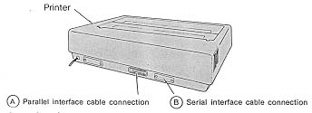
Parallel
Availability: Standard
Connection: Centronics
Activation: Automatic
Serial
Availability: Optional Card
Connection: RS-232C DB-25
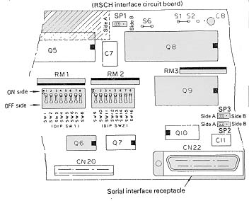
Serial board function
switches
| Switch |
Description |
Position |
Setting |
|
| 1 |
Parity Setting |
ON |
Odd |
        |
| |
|
OFF |
Even |
|
| 2 |
With/Without Parity |
ON |
Without |
|
| |
|
OFF |
With |
|
| 3 |
Data Bit |
ON |
8 bits |
|
| |
|
OFF |
7 bits |
|
| 4 |
Protocol Selection |
ON |
Ready/Busy |
|
| |
|
OFF |
X-ON/X-OFF |
|
| 5 |
Diagnostic
Selection |
ON |
Circuit Test |
 |
| |
|
OFF |
Monitor Mode |
|
| 6 |
Mode |
ON |
Print |
|
| |
|
OFF |
Diagnostic |
|
| 7-8 |
Busy Line |
|
see table below |
|
| 9-11 |
Baud Rate |
|
see table below |
|
| 12 |
Undefined |
|
|
|
| 13 |
Buffer |
ON |
32 bytes |
 |
| |
|
OFF |
256 bytes |
 |
| 14 |
Undefined |
|
|
|
| 15 |
Interface Selection |
ON |
Current Loop |
 |
| |
|
OFF |
RS232-C |
 |
| 16 |
Current Loop
Configuration |
ON |
2-wire |
 |
| |
|
OFF |
3 or 4 wire |
 |
| SW7 |
SW8 |
Setting |
|
| ON |
ON |
DTR (-12V) |
  |
| ON |
OFF |
RTS (-12V) |
|
| OFF |
ON |
SSD (-12V) |
|
| OFF |
OFF |
SSD (+12V) |
|
| SW9 |
SW10 |
SW11 |
Setting |
|
| ON |
ON |
ON |
19200 |
   |
| OFF |
ON |
ON |
9600 |
 |
| ON |
OFF |
ON |
4800 |
 |
| OFF |
OFF |
ON |
2400 |
|
| ON |
ON |
OFF |
1200 |
 |
| OFF |
ON |
OFF |
600 |
|
| ON |
OFF |
OFF |
300 |
|
| OFF |
OFF |
OFF |
110 |
|